HVACR Controllers
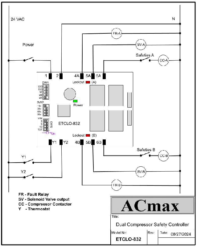
Dual Compressor Safety Controller, ETCLO-830
 |
The ETCLO-830 Compressor Safety Controller has an anti-short cycle, solenoid valve time delay and lead-lag multi-settings. It is designed for use with any single and two-stage air conditioning and refrigeration equipment for compressor operation and protection control. If during normal operation any safeties are opened (low or high pressure switches), the compressor will shut off immediately. The controller then restarts the A/C unit again and a warning flag will be set. The compressor will be locked-out if safeties are opened for a second time. Manually opening and closing the thermostat can restart the A/C unit and reset the board. The fault can be attended to at any convenient time. The early warning feature will save the compressor from burnout.
|
During normal operation of the compressor, contacts 5 and 6 will be energized, as well as the safety contacts that are in series with contact 6 and the compressor’s contactor. In this state, the warning flag (in the processor’s memory) will remain reset and normal operation will continue. If during normal operation safety contact(s) opens, the warning flag will be set and the compressor will shut off immediately. Terminals 5 and 6 will open for the duration of the selected anti-short cycle time delay (ASTD). Upon completion of this delay, contact 5, followed by 6, will re-energize. At this time there are two possible outcomes to this scenario: A - If the safety contact(s) is still open, the board will immediately go into lock-out mode, so that contacts 5 and 6 will be opened and the TRIAC output at terminal 4 (alarm output) will be activated. OR B - If the safety contact(s) is now closed, the compressor will start running again. However, the warning flag will remain set. If a safety contact(s) opens, the related compressor will immediately go into lock-out mode. Under condition B, the warning flag will be reset after 30 minutes of successful running of the compressor. In test mode, the 30 minutes for warning flag will be reduced to 4 seconds. When the thermostat is satisfied, the warning flag will be reset. The board is equipped with one green LED that indicates power to the board. Two red LEDs indicate the lock-out condition for each compressor. After power interruption, a unique time delay of 0–60 seconds for random start begins to avoid simultaneous start of multi-unit applications.
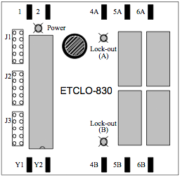
Terminal Designation
Jumper Settings Three sets of five position jumpers (J1, J2 & J3) are used to select functions as per tables below. Only one shunt should be applied to each jumper (except J3 in test mode).
The ETCLO-830 is designed for class 2 circuits and should be powered by an UL recognized class 2 24 VAC transformer. |
|


Single Compressor Safety Controller, ETCLO-848
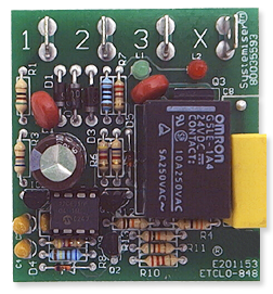 |
The ETCLO-848 Compressor Safety Controller with fixed anti-short cycle delay is designed for use with any single stage air conditioning and refrigeration equipment as compressor protection. If during normal operation any safeties are opened (low or high pressure switches), the compressor will shut off immediately, and then the controller manages the restart of the A/C unit and a warning flag will be set. The compressor will lock-out if safeties are opened for a second time. Manually opening and closing the thermostat can restart the A/C unit and reset the board. The fault can be attended to at any convenient time. The early warning feature will save the compressor from burnout.
|
When the thermostat demands for cooling, terminal 3 will be energized. Assuming that all safeties (HP & LP) that are connected in series with terminal 3 are closed, the warning flag (in the processor memory) will remain reset and normal operation will continue. If during normal operation (thermostat contact closed) any safeties contact(s) opens, the warning flag will be set, the compressor will be shut off immediately and terminal 3 will open. This state will remain for the duration of the selected anti-short cycle delay. Upon completion of the anti-short cycle delay, terminal 3 will re-energize. At this time, the controller monitors the operation of the safeties and takes decision based on: A - If the safety contact(s) are still open, the board will immediately go into lock-out mode, so that terminal 3 will be opened, and the TRIAC output at terminal X will be activated (board will go into lock-out mode). OR B - If the safety contact(s) are now closed, the compressor will start running again. The warning flag will remain set. If safety contact(s) opens, the board will forfeit the anti short cycle delay and will immediately go into lock-out mode. The warning flag will be reset after a 1⁄2 hour (30 minutes) of successful continuous compressor running. Also, when the thermostat is satisfied, the warning flag will be reset. The board is equipped with two LEDs. The green LED indicates power to the board. The red LED indicates the lock-out condition. |
|
Dual Compressor Safety Controller, ETCLO-832
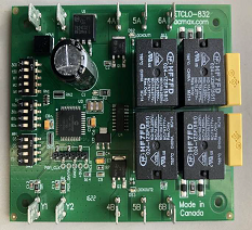 |
The ETCLO-832 Compressor Safety Control has an anti-short cycle, pump down solenoid valve time delay and lead lag multi settings. It is designed for use with any single and two-stage air conditioning and refrigeration equipment for compressor operation and protection control. If during normal operation, any safeties are opened (low or high pressure switches), the compressor will shut off immediately. The controller then restarts the A/C unit again and a warning flag will be set. The compressor will be lockout if safeties opened for second time. The A/C unit can be restarted manually by opening and closing the thermostat contact, which reset the board. The fault can be attended to at any convenient time. The early warning feature will save the compressor from burn out.
|
The ETCLO-832 is provided with full size Snap Track for easy installation.
|
|
Economizer Controller ET-792 & ET-793 - Psychrotroll
 |
A unique electronic controller design using one sliding damper to function as a return and fresh air mixing process instead of using two separate dampers. This design utilizes one actuator for one damper for both fresh air and return air. The controller is designed to operate a 12 VDC actuator to slide the damper to the required position. The controllers receive inputs from supply air temperature and outdoor temperature or enthalpy digital signal. One damper control system saves cost and space in the packaged air conditioning unit. |
Economizer controller ET-757
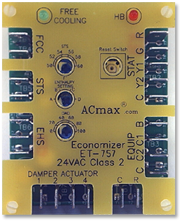 |
One of the challenges that HVAC design engineers face is developing an air conditioning distribution system to deliver outdoor air to the occupants of a building. This task involves determining whether the outdoor air is acceptable for a free cooling system, and then developing an air intake and mixing control system that will deliver the needed amount of outdoor air to the building at an acceptable cost. This challenge can easily be met with the Economizer Controller ET-757. This controller allows a cooling air handler to supply outdoor air instead of re-circulated air in order to reduce or eliminate the need for a mechanical cooling system during mild or cold weather. If the outdoor air is below the high enthalpy (humidity and temperature) point as set on the board, and based on an analog signal from the enthalpy sensor, the controller will lock-out the compressor (mechanical cooling) and modulate the return and outdoor air dampers to maintain the cooling set point. When the outdoor air enthalpy exceeds the high enthalpy set point, the outdoor air damper moves to the set minimum position for ventilation. The ET-757 meets the requirements of AINSI/ASHRAE/IESNA Standard 90.1-2001, “Energy Standard for Buildings Except Low-Rise Buildings”. Energy saving and improved air quality make the ET-757 attractive to HVAC design engineers and building owners, not to the mention the fact that a system with such a controller usually pays for itself within one or two years.
|
|
|


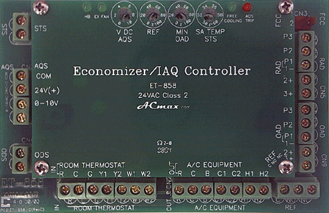
Economizer controller ET-858
|
One of the challenges that HVAC design engineers face is developing an air conditioning distribution system to deliver outdoor air to the occupants of a building. This task involves determining whether the outdoor air is acceptable for a free cooling system, and then developing an air intake and mixing control system that will deliver the needed amount of outdoor air to the building at an acceptable cost. This challenge can easily be met with the Economizer Controller ET-858. This controller allows a cooling air handler to supply outdoor air instead of re-circulated air in order to reduce or eliminate the need for a mechanical cooling system during mild or cold weather. If the outdoor air is below a high enthalpy (humidity and temperature) limit, typically 28 BTU/lb or 75°F db, the controller will lock-out the compressor (mechanical cooling) and modulate the return and outdoor air dampers to maintain the cooling set point. When the outdoor air enthalpy exceeds the high limit set point, the outdoor air damper moves to the set minimum position for ventilation. ET-858 can also control the amount of fresh air needed for ventilation by means of an analog signal from an indoor air quality sensor. This is to meet the Demand Control Ventilation (DCV) requirement. The indoor air quality sensor (typically CO2 sensor) determines the demand for fresh air based on the occupancy of the building by measuring the amount of CO2 (unlike a fixed rate of fresh air for maximum occupancy). The ET-858 meets the requirements of AINSI/ASHRAE/IESNA Standard 90.1-2001, “Energy Standard for Buildings Except Low-Rise Buildings”. More details on DCV can be found at the Learning Centre. Energy saving in DCV and improved air quality make the ET-858 attractive to HVAC design engineers and building owners, not to the mention the fact that a system with such a controller usually pays for itself within one or two years.
|
|
|
Temperature Controller, E610
 |
The E-610 may be used as a simple temperature controller, providing on/off relay output for fans, heaters, shut off valves and alarm systems. Because of its software adjustable parameters, the product is highly customizable - an ideal solution for many OEM temperature control applications.
|
The E-610 is a temperature controller with the ability to act as an ON/OFF temperature thermostat.The device is capable of fully stand alone operation. The unit may be programmed(preset in the factory) in one of three control modes: (a) temperature range mode in which it will turn ON the output relay between two defined temperatures (b) set point mode for heating mode iin which it will turn ON below adefined temperature and OFF above a defined temperature (c) set point mode for coolingmode in which it will turn ON above adefined temperature and OFF below a defined temperature |
|
Power switching relay board (24 VAC, 5 RELAYS), ET-788
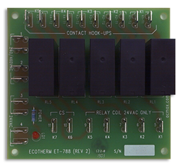 |
The ET-788 relay board is designed to convert 24VAC control signals to 240VAC dry contacts to operate 3-speed fans, compressors, heater relays, and other line voltage devices.
|
|
|
Power switching relay board (24 VAC, 5 RELAYS), ET-854
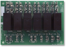 |
The ET-854 relay board is designed to convert 24 and 240VAC control signals to 240VAC dry contacts to operate 3-speed fans, compressors, heater relays, and other line voltage devices.
|
|
|