Demand control ventilation (DCV)
 Carbon Dioxide (CO2)-based demand controlled ventilation (DCV) is increasingly used to modulate outside air ventilation based on real-time occupancy. Measurement and control technology using CO2 sensors is quickly evolving to a stage of maturity where cost and reliability will likely approach that of conventional temperature measurement and control in the near future. As a result, the use of CO2 as an indoor comfort, ventilation and air quality control parameter has the potential to become as common as thermostatic control is today. Like any other control system, the success of CO2-based DCV application is dependent on how it is engineered, installed and maintained.
An indoor CO2 contaminant level provides a dynamic measure of the balance between CO2 generation in the space, representing occupancy, measured in part per million (ppm) and the amount of low CO2 concentration outside air introduced for ventilation. The net effect is that it is possible to use CO2 concentration to determine and control the fresh air dilution rate in a space on a per person basis.

CO2 is one of the most common gases found in our atmosphere. As a point of reference, concentration in the center of the Pacific Ocean has been measured at 366 ppm and this is considered as the lowest concentration found worldwide. In urban areas, outdoor concentrations have been in the 375 to 450 ppm range.
CO2 is not considered harmful nor a contaminant at the levels of 400 to 2000 ppm normally found in buildings. Perceptions of poor air quality associated with elevated CO2 levels are more indicative of the buildup of other contaminants as a result of reduced per person ventilation in a space rather than the direct effect of CO2. All humans, given a similar activity level, exhale CO2 at a predictable rate based on occupant age and activity level. This relationship is described in ASHRAE standard 62. For HVAC applications, CO2 is best used as an indicator for fresh air ventilation on a per person basis.
The relationship between CO2 production and body odor is that CO2 levels increase or decrease in relation to human metabolic activity. Since CO2 is a good indicator of human metabolic activity, it could also be used as a tracer for other human emitted bio effluents. High levels of CO2 can cause nausea, headaches and dizziness. Adults usually can tolerate CO2 concentration of 1,000 ppm, and children usually can tolerate 500 ppm. Outside air dampers should open to allow enough air to enter a building to keep the CO2 level below 1,000 ppm.
As this technology has developed, so have codes and standards. The International Mechanical Code (IMC), the mechanical code of reference for most local building code bodies in the United States, has included provisions for CO2-based DCV. IMC codes states that “The minimum flow rate of the outdoor air that the ventilation system should be capable of supplying during its operation shall be permitted to be used on the rate per person indicated in their standard and the actual number of occupants present.”
Also ASHRAE standard 62 has clarified the use of CO2 as a parameter that can be used for controlling ventilation based on actual real-time occupancy while still maintaining target cfm-per-person ventilation rates.
CO2– based DCV does not affect the design ventilation capacity required to serve the space; it just controls the operation of the system to be more in tune with how a building actually operates.
Excessive over-ventilation is avoided while still maintaining good Indoor Air Quality (IAQ) and providing the required cfm-per-person outside air requirement specified by codes and standards. The ASHRAE Technical Committee has observed operational energy savings. This observation has been verified in a recent literature review on CO2 control that cited studies where energy savings form DCV control approaches ranged from 5% to 80% versus a fixed ventilation strategy. System paybacks can range from a few months to two years and are often substantial enough to help pay for other system or building upgrades. The payback from CO2–based DCV will be greatest in higher density spaces that are subject to variable or intermittent occupancy that would have normally used a fixed ventilation strategy (e.g., theaters, schools, retail establishments, meeting and conference areas). In spaces with more static occupancies (e.g. offices), CO2–based DCV can provide control and verification that adequate ventilation is providing to all spaces. For example, a building operator may arbitrarily and accidentally establish a fixed air intake damper position that results in over or under ventilation of all or parts of a space. A CO2 control strategy can ensure the position of the intake air dampers is appropriate for the ventilation needs and occupancy of the ventilated space at all times. This may save additional energy when outside air intakes are arbitrarily set to over-ventilation.
In some buildings, infiltration air or open windows may be a significant source of outside air. A CO2 sensor will consider the contribution of infiltration in a space and only require the mechanical system to make up what is necessary to meet required ventilation levels. The savings are in addition to those quoted earlier. When integrated with the appropriate building control strategy, ventilation can be controlled zone by zone based on actual occupancy. This allows for the use of supply air from under-occupied zones to be redistributed to areas where more ventilation or cooling is needed.
A CO2 control strategy can be issued to maintain any per-person ventilation rate. As a result this approach is highly adaptable to changing building uses and any changes that may occur in future recommended ventilation rates.
(For more information on DCV Controller, please click ET-858 product).
General Guidelines
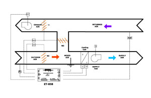
The objective of a CO2 control strategy is to modulate ventilation to maintain target cfm/person ventilation rates based on actual occupancy. The strategy should allow for reduced overall ventilation during periods of occupancy that are less than full occupancy and as a result save energy. Typical control approaches have used a proportional control algorithm to modulate ventilation between a base ventilation rate established non-occupant-related sources and the design ventilation rate for the space. Modulation of outside air above base ventilation begins when indoor CO2 is above the high limit set by the CO2 sensor. The outdoor damper OA modulates above the minimum setting of the OA damper.
Duct mounted CO2 sensors are best used where a single space or when multiple spaces with common occupancy patterns are being ventilated. The most common area of installation is directly in the return air ductwork or inside the return air plenum.
Wall mounted CO2 sensors are recommended for multiple units installation where the return air may not be representative of what is actually happening in the particular space.
In setting the minimum outdoor damper, ventilation rates should not be reduced below 20% to 50% of design. Maintaining this minimum rate supplies sufficient ventilation air to dilute building contaminant sources, even at low occupancy levels.
Most of the CO2 sensors have analog output of 0-10 VDC or 4-20mA correspond to 0-2000 ppm CO2 concentration. Setting values of the CO2 level on the economizer/IAQ controller should be based on the difference between the maximum designed outside air and the minimum setting on the OA damper.
When to Use Outdoor Air CO2 Sensing
CO2-based demand controlled ventilation is based on the principle that the differential between inside and outside concentrations can give an indication of the ventilation requirement rate in the space. As a general rule of thumb, an inside/outside differential of 700 ppm is indicative of a ventilation rate of 15cfm/person (7 L/s). An inside/outside differential of 500 ppm is indicative of a 20 cfm/person (9 L/s) ventilation rate.
For most applications, outside air can be assumed to be at 400±50 ppm. As a result most control strategies will work well if the designer or installer assumes outside levels are at 400 ppm. Even if outside concentrations are higher than 500 ppm, and 400 ppm is used as the assumed outside level, the only impact will be that the space will be slightly over ventilated by about 2 cfm/person (0.9 L/s) during those periods when outside levers are elevated. Since the lowest levels are approximately 366 ppm, a conservative maximum under-ventilation effect of assuming a 400-ppm outside level is less than 1 cfm per person (0.47 L/s).
Elevated outside CO2 levels are generally due to the presence of localized combustion sources such as vehicles, power plants, or building exhausts. If elevated levels are measured, it may be a function of the location of outside air intakes related to localized combustion sources. In these applications and if deemed necessary by the designer, CO2 sensors are installed outdoor to ensure that ventilation rates are controlled based on real-time differential between inside and outside CO2 concentrations.
Setting of the Outdoor Air Damper for the Minimum Outside Air
By knowing the temperature of the outside air and the temperature of the return air, you can determine the temperature of the mixed air that enters the inlet side of the supply blower.
Use the following equation:
MAT= (OAT x %OA) + (RAT x %RA)
Where
MAT = mixed air temperature
OAT = outside air temperature
%OA = % of outside temperature
RAT = return air temperature
%RA = % of return air volume
Let’s say that the temperature of the return air is 80†F, and that the temperature of the outside air is 40†F. Assume that you’re working on a building that requires a mixture of 10% outside air and 90% return air.
Then:
MAT = (40†F x 0.1) + (80†F x 0.9) =
4 + 72
= 76†F
Now you know that the temperature of the mixed air should be 76†F.
If you are commissioning a 10-ton unit that moves 4,000 cfm of air, you also know that you want about 400 cfm of outside air (10% of 4,000).
Measure the temperature of the air at the blower inlet. If the mixed air temperature is above 76†F, then the amount of outside air is less than 10%, or 400 cfm. If the mixed air temperature is below 76†F, then the amount of outside air is more than 10%, or 400 cfm. In either case, you can adjust the dampers accordingly. Within a short period of time, you can take another temperature reading to determine whether the dampers have been adjusted properly.
Why Compressors Fail
Compressor failure is a common problem in the HVAC&R industry. It inconveniences suppliers and customers as well as costing time and money. The two basic causes of compressor failure are: an incorrect or non-diagnosis and improper installation or maintenance of the compressor.
Very often, a compressor fails because of an external problem. More than 60 percent of all failures are caused by system and service-related problems. Yet more often than not, a compressor will be replaced without the service person determining the actual cause of the failure. As expected under such circumstances, the new compressor will eventually fail as well at rate several times higher than for original installation.
For the majority of compressors, which do not fail in 15 years, there must be a condition of part variation that withstands all of the applied operating conditions. Other compressors with more serious variations eventually experience the operating condition that will cause failure.
Compressors, operated within their limits, do not wear out. In one documented instance, a compressor ran more than 30,000 hours and 16,000 cycles. When it was subsequently torn down and all its parts were measured, they were found to be still within new compressor specifications and tolerances.
Then why do compressors fail? Two extreme cases may lead to a general conclusion. First, a compressor can be subjected to abusive conditions, such as a harsh tropical environment. Extremes of temperature or pressure can eventually make any compressor fail. Other potential abuse situations would include a loss of oil and/or a loss of refrigerant charge. Secondly, a compressor can contain a gross manufacturing defect.
Compressors fail because of: a loss of Lubrication; flooding; flooded starts; slugging; contamination; overheating; and/or electrical problems. Oil does not return at a satisfactory rate when there is: a low, refrigerant velocity, short cycling, low load, traps or piping errors.
Airside problems are known to be a significant cause of flooding. They include broken evaporator fan belts, bad fan motors, dirty coils, and dirty filters. A dirty condenser coil or a failed condenser fan motor allows heat to build in the coil rather than being rejected into the atmosphere. The compressor then has to pump against excessive pressure, which may cause it to overheat, resulting in accelerated component wear, damage, or complete failure.
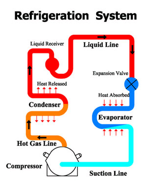
One method of minimizing refrigerant accumulation in the compressor, or a flooded start, is to incorporate a pump down control system. In this system a solenoid valve can be installed in the liquid line. The compressor pumps down the system and a low-pressure switch stops the compressor after the refrigerant has been removed from the low side of the system. The compressor restarts, after a time delay, when the thermostat energizes the solenoid valve again.
Unbalance of voltage and/or current can lead to electrical problems, which in turn causes compressor failure. Both voltage and current anomalies cause an increase in temperature, which may go unnoticed for a long period of time.
There are several things that can be done to help prevent repeat compressor failures, such as: improving equipment maintenance and record keeping; using proper start-up procedures; improving systems and diagnostic skills; and inspecting the failed compressors. A proper diagnosis as to the cause of the failure is also essential.
As mentioned previously, compressors are designed to handle normal thermal temperature gain. However, when they are operated outside their design conditions, careful attention has to be taken to avoid reduced life expectancy and potential damage.
If the equipment/systems do not have proper operating and safety protection and monitoring devices, problems can go undetected until the compressor burns out.
Cost-effective operation and maintenance require implementing new technology, installing electronic protective devices to monitor and to warn about the repeated tripping of the compressor.
(For more information on Compressor Safety Controller, please click ETCLO-830).